In real projects that iterate continuously, the frontend codebase usually already has established components, page structures, and business logic. Facing constantly updated Figma design files, how to restore them stably into the existing codebase while avoiding damage to the original code structure and business operation is the core problem we face in practice.
The core of this practice is to use an Agent to turn restoration from design files to frontend code into an engineering pipeline that can run repeatedly and be verified. Under real engineering constraints, design files are often not fully standardized, the code of the existing codebase cannot be rewritten at will, and the cost of repeated iteration and the visual result both need to be clearly verifiable. The trade-offs and mechanism designs made under these constraints form the foundation that enables this pipeline to keep running.
Starting from the problems encountered in actual iteration, the following sections follow the main thread from input constraints, version reuse, and visual verification to the boundary of legacy pages, introducing in turn the rules and mechanisms we established at each stage, and how these mechanisms connect into a complete restoration pipeline.
Five categories of frequently occurring restoration problems
In actual iteration, we encountered the problem that adding a filter module to a legacy page easily led to the entire page being rewritten. The requirement was originally only to add a filter module to an existing page, but during automated restoration, the generation pipeline often rewrote the entire area including the existing page with base-level code.
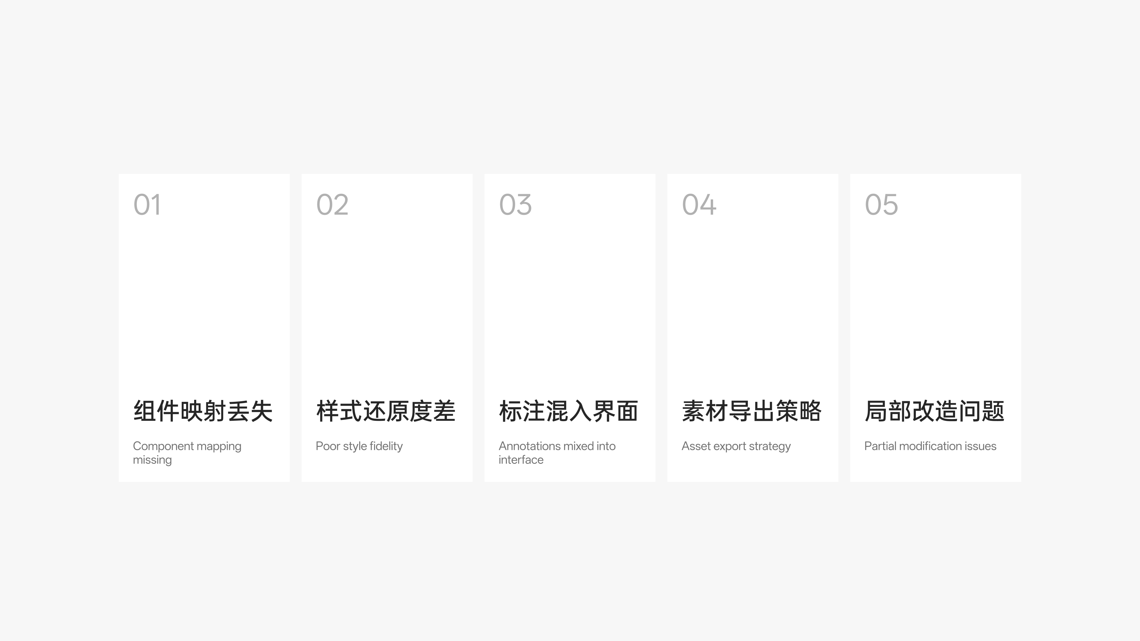
This phenomenon prompted us to re-examine the pipeline mechanisms in automated restoration. In advancing from Figma to real frontend code, there are mainly five categories of problems:
The first is the loss of design semantics. In design delivery, components in the design file may be detached. Once the component association is detached and the recognizable component semantics weaken, the code generation pipeline cannot directly obtain the original general component information, and easily degrades into extracting coordinates, colors, and dimensions to directly generate base-level structures and styles.
The second issue is the difficulty of unifying styles across multiple pages. Local restoration of a single page is usually easier to handle, but when dealing with multiple consecutive pages, if there is a lack of coherent style and structural constraints, the code generated for different pages will struggle to maintain the same design language, and inconsistencies in spacing, font size, and color configuration are likely to occur.
The third is the confusion between annotation information and the real interface. To explain interaction logic, design drafts often contain annotation text or explanatory areas. Without a clear distinction mechanism, the code generation process struggles to tell which content is explanatory and which is the real interface that needs to be rendered, and it is easy to write the explanatory copy into the page code as well.
The fourth is the ambiguity of the asset export strategy. Whether graphical assets in a page need to be exported, in what format, at what export scale, and whether they are placeholder resources—if there are no structured expression rules on the design side, the code generation process lacks a basis, and asset handling is likely to become chaotic or placeholder resources may be incorrectly packaged.
Finally, there is the issue of full overwriting during partial modifications of legacy pages. When partial additions or deletions occur on an existing page, if the boundaries of the change cannot be clearly defined, the generation process may mistake a partial adjustment for a full refactor, and then rewrite the existing logic and structure in the existing project.
These five categories of problems show that design semantics, information organization, change scope, and verification methods need a unified mechanism constraint established between design draft input and front-end engineering implementation. Among them, repeatedly acquiring and translating design information also increases iteration cost, becoming the direct reason for subsequent Loop adjustments.
Implementation Constraint Layer
Before generating code, a layer of implementation constraints oriented toward front-end engineering must first be established. Design drafts in real business scenarios are often not fully standardized—layers may be unnamed or components may be detached; meanwhile, existing projects have their own mature component libraries and design systems. Without constraints, an Agent can easily guess the implementation approach based solely on visual appearance, degrading into generating native tags or writing styles arbitrarily. Therefore, implementation constraints need to be introduced between design input and code generation, defining generation boundaries for the Agent from three dimensions: global principles, capability retrieval, and boundary correction:
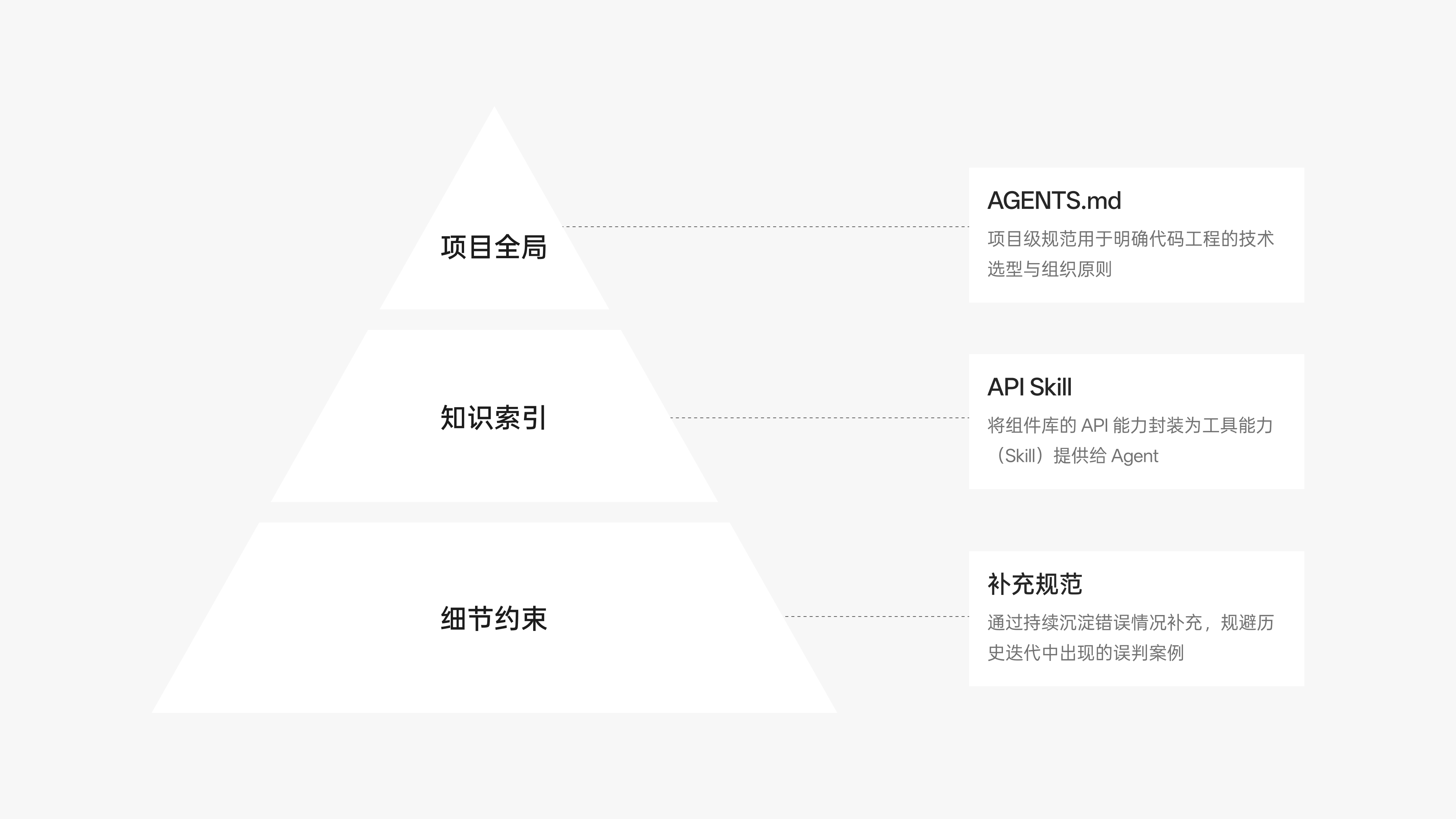
Project-Level Specifications
Project-level specifications are used to clarify the technical choices and organizational principles of the code project. In AGENTS.md in the project root directory, we specify in a machine-readable way the reuse requirements for front-end components, clearly stipulating that whenever a capability can be mapped to the existing component library, existing components should be reused first and construction should be based on the project's existing design system.
Knowledge Index
With specification requirements in place, the executing party must also be able to retrieve specific capabilities. We established a structured knowledge index and encapsulated the component library's API capabilities as tool capabilities (Skills) provided to the Agent. When facing interface structures, the executing party can proactively query the component library's type definitions, supported property combinations, and standard slot usage, rather than guessing the implementation approach based solely on appearance.
Supplement on Error Cases
Real-world engineering always encounters non-standard, edge-case scenarios. By continuously accumulating supplementary error cases, we turn misjudgment cases, easily confused styles, and special adaptation logic from past iterations into negative rules and an edge-case index, preventing the same parsing errors from recurring in subsequent tasks.
These three work together: project-level specifications provide global principles for component reuse, the knowledge index provides a queryable view of real engineering capabilities, and supplementary error cases correct deviations that have already occurred, jointly constraining the visual intent expressed in the design draft within the technical track of the existing engineering.
Component mapping: semantic judgment and real API confirmation
After establishing the implementation constraint layer, the core action is to solve the mapping from design draft nodes to code components. The lesson we have drawn from this mechanism is: divide "semantic judgment" and "real API confirmation" into two layers that follow one another in sequence.
In the first layer, the component mapper focuses on abstract semantic judgment, analyzing the functional roles of regions and elements; then the second-layer provider steps in, mapping this abstract role onto the real component library used by the frontend engineering, confirming the specific component name, property parameters, style tokens, and version.
The reason for this two-layer split is that when design drafts enter implementation, they are often in one of four non-ideal states: unnamed, confusingly named, detached nodes, and lacking auto layout. Under such non-standard inputs, if the parser is expected to translate directly into final code components in one step, it is prone to hallucination or simply giving up on component reuse.
During the mapping process, the set of capabilities that need to be checked first includes: props, variants, slots, design tokens, composition, and state response capability. Whenever a capability can be mapped to the existing component library, the existing component is reused first.
We can look at this inference process through three illustrative examples:
Determining an outlined button
In the design draft, when facing a detached button, the layer may simply be a rectangle with centered text. The first-layer mapper first identifies it as a button-type control that needs interaction, rather than directly hardcoding it into some specific code style. Then the second-layer provider steps in, queries the Button component in the component library, and confirms the specific property configuration used in the current component library to express the outlined style, thereby generating code that reuses the component, rather than outputting a native button tag with native border styles.
Dividing the internal regions of a modal
In a business modal, the design draft may be composed of multiple rectangular containers. The first-layer mapper first determines that the whole is a modal overlay and divides its interior into a Header title area, a Content scrolling content area, and a Footer action area. The second-layer provider then maps these regions respectively to the modal subcomponents and slots of the real component library, reusing the existing capabilities that the component library provides for this kind of structure.
Confirmation of icon roles
For graphical elements that appear in input box or button areas, the first-layer mapper determines, based on their position and container relationship, whether they are accompanying action icons or decorative graphics. At the second layer, the provider matches the corresponding icon component based on naming clues and the project's existing icon capabilities, thereby importing icons from the component library instead of inlining a hard-to-maintain native vector code snippet.

Through this dual-layer decoupling, the code generation process reduces its dependence on absolute coordinates and native HTML/CSS. In tests also using Codex with GPT 5.4, the correct component invocation rate increased from about 50% to nearly 100%.
Annotation protocol: separate descriptions from the real design draft
Having solved the recognition of components themselves, the next step is handling auxiliary information on the canvas. In real design workflows, business descriptions and state-transition indicators are often distributed across the artboard. If this content is mixed together with the real interface, automated tools will experience recognition drift.
To clarify the information, we implemented a standard annotation protocol. We use two lightweight Figma plugins to handle the auxiliary marking work of design annotations and asset naming, respectively, and through conventions combined with prompt constraints on the Agent side, we achieve separation of descriptions from the interface.
In terms of structural organization, all content that needs to be recognized by engineering follows explicit prefix conventions: business descriptions and interaction guidance uniformly use {guidance Frame name}/Figma Annotation/ as the prefix; while the actual interface drafts to be implemented use {guidance Frame name}/ as the prefix. The entry relationships of interfaces are likewise expressed by naming prefixes. Through explicit isolation in container naming, the parsing process can distinguish which information is only used to understand business flow and which structures are view baselines that need to be actually rendered in code.
When implementing this protocol, there is an error-prone point: annotation containers can nest real design drafts. In actual drawing, for compact layout, a design draft sometimes embeds within an annotation description card a sub-interface fragment or partial form that needs real implementation. If the parsing logic simply ignores the entire container with the annotation prefix, the real interface draft nested inside will be discarded along with the description text.
Therefore, prefix parsing must be able to recognize the description text within the annotation prefix while not discarding the nested real design draft along with it. Distinguishing by naming prefix both extracts the description copy as contextual clues for understanding interactions and preserves the real interface structure nested within.
Asset strategy: three types of tags determine export behavior
After separating interfaces from annotations, deterministic export rules need to be established for the graphical assets contained within interfaces. If the model is left to judge on its own whether a graphic should be exported as vector, exported as bitmap, or treated as a placeholder, the results are often unstable.
Through an auxiliary plugin, we introduced three types of tags into the layer naming of design drafts, directly determining resource handling behavior during downstream code generation:
<icon>: identifies vector icons, which the parsing pipeline exports directly as SVG;
<img>: for actual visual assets such as illustrations, exports 3x PNG, with a later optimization to export compressed WebP;
<export_null>: identifies placeholder images,indicating that this placeholder image does not need to be exported.
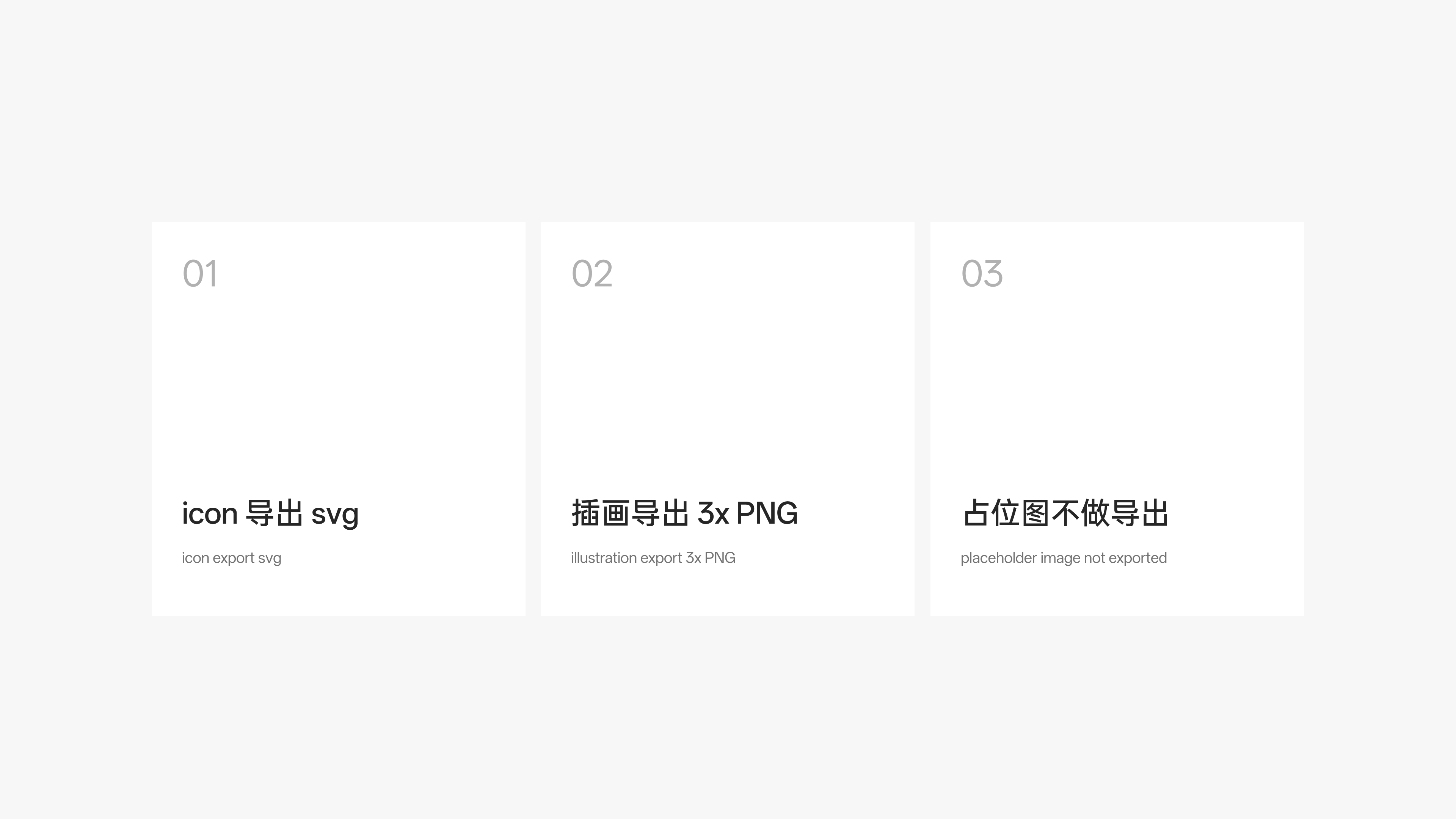
These tags move decisions about whether to export, which format to use, and the export scale to the design side in advance, so the Agent can process assets accordingly.
After this naming protocol around annotation prefixes and asset tags was implemented, our engineering records showed a 100% test compliance rate for annotation and asset rules; after 5.6 sol, no negative feedback was received in the following months.
The cost of Loop: why the quota was burned through early on
Once we had straightened out the semantic mapping and annotation protocol, we tried to build an automated iteration loop (Loop): let the Agent read the design file, generate code, run the project, and compare the interface, and if there were discrepancies, keep modifying to form a self-correcting closed loop.
However, in early experiments, after only a few rounds of page iteration and restoration, the monthly quota at the time was exhausted.
Looking back at the reasons for the consumption at the time, the problem lay in the fact that each round of the closed loop had to re-request design information and re-translate it; repeated requests and translations stacked up and caused spending to accumulate rapidly.
In an automated closed loop, code tweaks are often aimed at small local details. Take a small change as an example, such as adjusting a 2px margin or changing a text color value; such code changes usually involve only a few lines or even a few characters. But because the initial closed-loop logic tightly coupled obtaining the design baseline with code generation, in order to verify whether a tweak took effect, the system would re-initiate data requests to the design source in every round of tweaking and re-translate the retrieved node data into code context.
Under this mechanism, the upstream design source did not change at all during tweaking, and the data provided was exactly the same as in the previous round, yet every local attempt downstream was forced to repeatedly process the same design input. The higher the frequency of local adjustments, the faster the overhead of repeated requests and repeated translations accumulated, ultimately exhausting the monthly quota at the time after just a few rounds of restoration. Without breaking this practice of reorganizing the design context in every round, the tweaking loop would be unsustainable in terms of cost.
Centralized collection per batch per version with timestamped version snapshots
Faced with this resource consumption, we adjusted data collection and context organization, decoupling the dynamic comparison and design collection parts from the engineering pipeline.
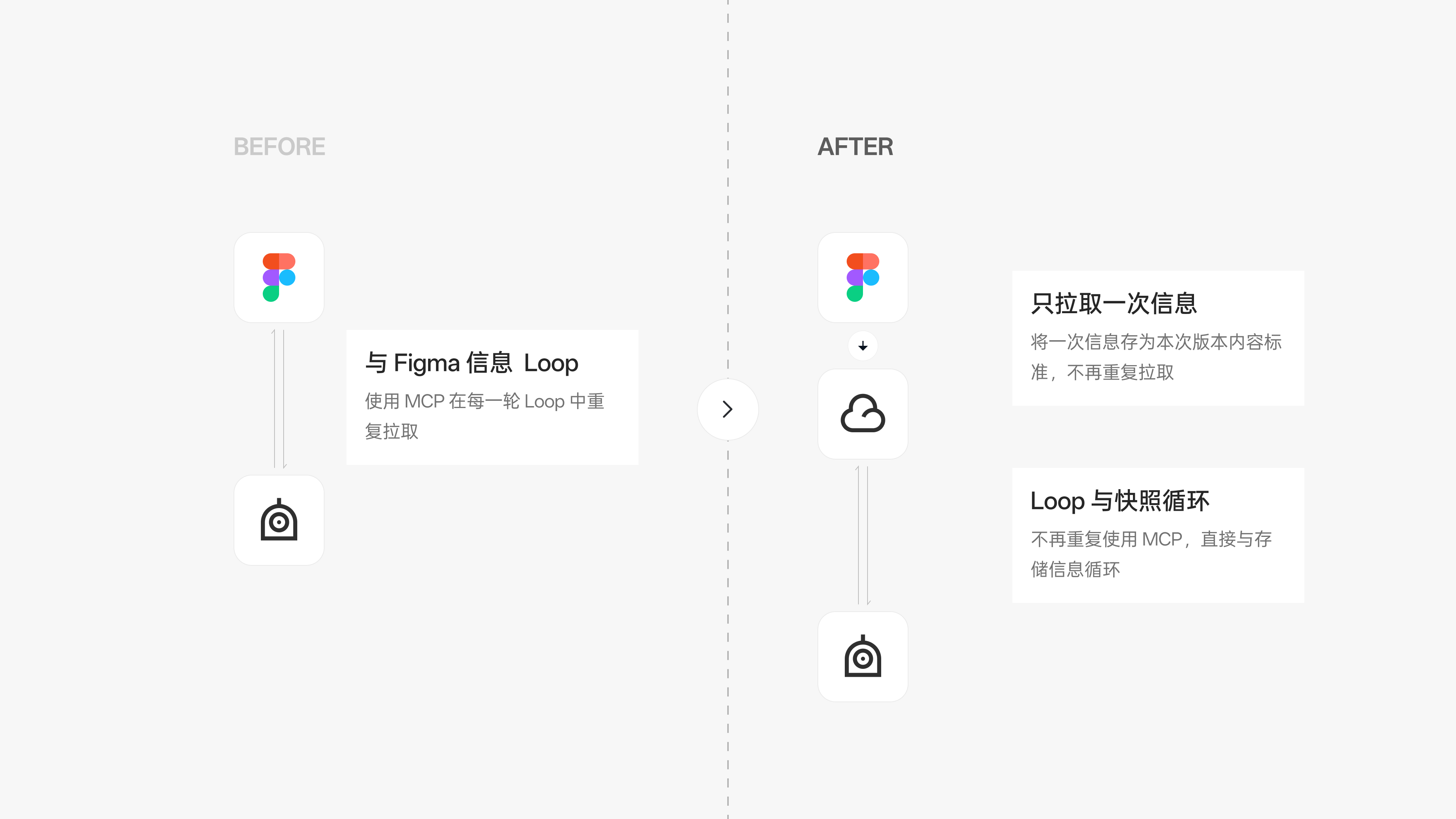
We adjusted the practice of pulling design drafts in real time within the fine-tuning loop, switching to a batch version mechanism: for the same batch of design content, each version is collected once in a centralized manner, and the translation results are saved on the server as timestamped version snapshots; all subsequent comparisons and fine-tuning for the same version directly reuse that snapshot, without repeatedly pulling from the design source; when the design is genuinely updated, a new timestamped version is created separately.
Fixed versions also provide a stable basis for multi-round comparisons. If the closed loop always relied on real-time pulling from the design source, then once the design canvas undergoes temporary changes, the reference basis for code generation would drift,and the comparison conditions between the previous round and the next round might differ.At the same time, the high frequency of external requests would also hinder the routine operation of the closed loop.
This adjustment reflects a clear engineering trade-off: we deliberately gave up sensing immediate design draft changes within a single fine-tuning loop. Within a specific version cycle, temporary changes on the canvas will not be synchronized into the code closed loop currently being executed. The boundary of this trade-off lies in: the timestamped version snapshot saves and reuses the design content and its translation results, and its responsibility is to provide a static, stable comparison benchmark; whereas the actual front-end code implementation is the dynamic object that evolves dynamically, is continuously compiled, rendered, and used for comparison. By solidifying the translation results into snapshots, code fine-tuning can always be reasoned upon anchored to a definite baseline, while external repetitive overhead is effectively blocked.
In actual engineering practice, this approach significantly saves tokens and time; when Codex uses the 5.5 model, the restoration fidelity exceeds 90%.

Making comparison valid: state, viewport, data and DOM Bounds
With a stable snapshot as the design baseline, the next step is to clarify the specific conditions for comparison.
If the project is run locally to capture images and compare them with design drafts, invalid errors are likely to arise in real web pages. The reason comparison must satisfy a series of strict preconditions is that visual differences are often caused by a mix of multiple environmental factors; if irrelevant interference is not eliminated in advance, the comparison results cannot truly reflect the restoration quality of styles:

Unified browser viewport
Before comparison, we first unify the browser viewport so that the implementation page renders at the agreed available width and height.Modern frontend pages generally use fluid typography and flexible layouts, and container dimensions and line-wrapping behavior are directly constrained by the size of the browser viewport. If the browser viewport width of the implementation page is inconsistent with the viewport set by the design baseline, then even if the CSS code fully complies with the specification, elements will be forced to wrap or stretch because the available width changes. If this kind of layout change caused by inconsistent viewports is misjudged as a style error and handed to the Agent for repair, it will incorrectly modify padding or fixed widths that were originally correct, leading to even more layout confusion. Therefore, it is essential to ensure that the page renders under a unified browser viewport configuration.
Target state transition
Real business interfaces are often in specific interaction states, such as an expanded dropdown menu, a popover, or a form validation state. Design mockups usually show these final states with specific interactive content, whereas the page is in the default initial state immediately after loading. If the initial page is directly compared with the final-state design mockup, the entire activated area in the diff image will be judged as an error. This is not a style implementation defect, but rather because the page has not yet stepped into the target interaction node. The automation script must first drive the page to simulate interaction, enter the corresponding target state, and then perform the comparison, so that both sides are on the same logical cross-section.
Fixed data and scroll position
The number of list rows, text content, and scrollbar position of the interface need to be fixed. If the number of data rows returned by the local runtime environment differs from the design mockup, or if there are differences in text character lengths, the height of the entire container and the internal flow layout will change. Changes in the number of data rows will cause the diff to change; such differences cannot all be blamed on CSS style errors. If Mock data is not fixed, the system will try to barely align heights by compressing component spacing or adjusting margins, causing the code to deviate from existing specifications. Similarly, scroll position offsets will also cause global pixel misalignment, so screenshot comparison must be performed at the same scroll anchor point, keeping the comparison focused entirely on the visual implementation itself.
Theme and load completion conditions
Before comparison, the page needs to ensure consistent theme settings and satisfy load completion conditions: stylesheets injected and ready, charts and fonts rendered, and skeleton screens dismissed. The initial page load is often accompanied by a transition phase of font replacement and asynchronous resource loading. If a half-finished screen is captured too early, the comparison engine will treat the temporary placeholder state as an interface defect and produce a false positive. Therefore, comparison must be triggered only after the page has fully reached a static stable state.
The role of DOM Bounds in localization
Pure image difference comparison can only point out regions where pixels are inconsistent on the screen, and cannot directly explain the underlying structural cause. For example, if a component is displaced on the screen, pixel differencing can only show a large area of color mismatch, but cannot explain whether the component's own margin settings are wrong, whether a change in the size of an adjacent sibling element caused a push, or whether the parent container's padding is missing. The role of DOM bounds detection in the comparison loop is to extract the box model geometric boundaries of key nodes in the real render tree, provide position and size evidence for the loop, and assist in locating the specific DOM node where the difference lies, so that subsequent code fine-tuning can be carried out based on geometric boundary evidence.
Visual loop: six-step execution and difference recording
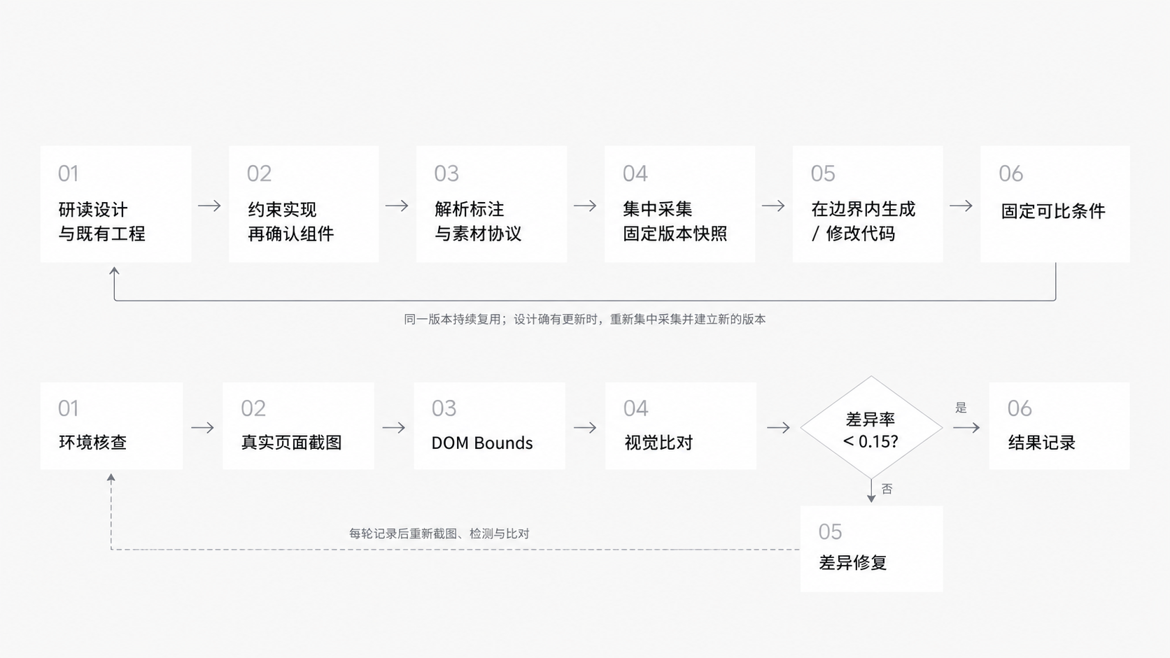
After unifying the baseline snapshot and comparison conditions, we organized the verification process of frontend reproduction into a six-step loop process:
The first step is environment verification, verifying the browser viewport, Mock data, and baseline configuration to ensure the runtime environment is in the preset state; the second step is real page screenshot, driving the page to step to the target state and capturing the actual rendered image; the third step is DOM bounds detection, extracting the geometric box model boundaries of key nodes in the render tree to obtain position and size evidence; the fourth step is visual comparison, comparing the real page screenshot with the design snapshot, and outputting a difference image and structured difference data; the fifth step is difference fixing, where the Agent combines the difference data and DOM boundary information to make targeted fine adjustments to code and styles; the sixth step is result reporting, outputting the difference record and convergence metrics of this round of adjustments.
These six steps each have their role: environment verification ensures consistent comparison conditions, real page screenshots present the actual results in the browser, DOM bounds supplement position and size evidence, and the difference image and JSON report record deviations. After fixing, comparing again under the same conditions is the only way to determine whether this round of modification is effective. A passing build only means the project can be built; whether the visuals are aligned still needs to be checked in the real page.
For quantitative evaluation of interface differences, the engineering record uses the difference rate to measure comparison results, with 0.15 as the visual convergence threshold for this process.
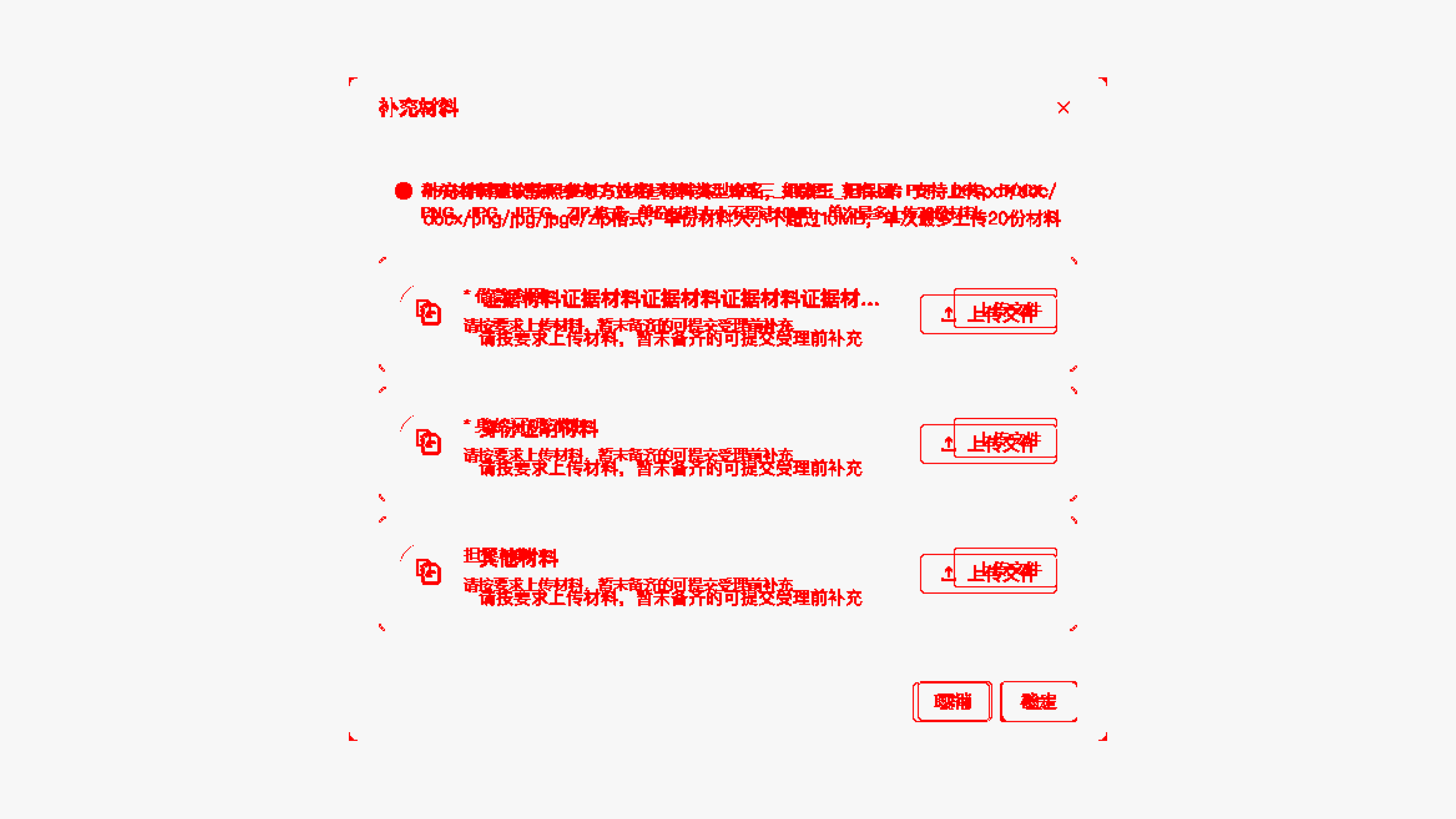
The following is the data of two cases in the engineering record:
Page / Module Type | Reference size (width × height) | Actual implementation size (width × height) | Final recorded difference rate |
|---|---|---|---|
Material modal | 608 × 532 | 608 × 532 | 0.09788 |
Details page | 1442 × 1878 | 1442 × 1878 | 0.08329 |
Both tests assume alignment between reference and implementation sizes, and both cases reached that threshold, with difference rates below the convergence threshold set for this process. This indicates that, under strictly controlled comparison conditions, the closed-loop process can support local fine-tuning and convergence.
Local modification of legacy pages: how to draw boundaries
After clarifying the comparison mechanism, when facing local modification requirements for legacy pages, defining the modification boundary is key to ensuring engineering stability. This is also the core of solving the problem that adding modules to a legacy page easily leads to the entire page being rewritten.
Local modification of legacy pages is prone to scope creep because of cognitive differences between design expression and engineering implementation. Existing pages usually already carry real business operations online and have accumulated complex state management, interface contracts, and business logic. Design drafts mainly carry layout, visuals, and visible states; interfaces, permissions, and business rules have other sources and are not inferred from design drafts. If clear boundary constraints are lacking, when the generation process faces a design draft containing a complete page, it easily assumes that everything it sees needs to be implemented from scratch, thereby overwriting the original mature logic.
Before writing code, first study the design draft and the existing project, confirm the target page, and identify reusable modules. For requirements involving multiple pages, proceed one page or independent feature at a time: in each round, clarify the current scope, use the corresponding version of the design baseline, compare under the same page state, and then fix according to differences. Snapshots reduce the cost of repeated collection and translation, scoped execution makes each round more focused, and the visual closed loop checks whether styles are gradually aligned.
Local adjustments to legacy pages also require clarifying four conventions:
Existing page
Explicitly lock in the existing file and mount location to which this change belongs. This convention guards against context drift and loss of control away from the main trunk. When the requirement is merely to add a module to an existing page, if the specific code file path is not explicitly specified, the generation process, when faced with the full-page design context, tends to create a parallel set of page code in an unrelated directory on its own. Although the new page looks visually complete, it is completely detached from the project's existing routing system and global state. By explicitly locking the file path of the existing page, changes are forced to be anchored to the code nodes of the existing project.
Target area
Clearly delineate the scope container for the change. This convention guards against cascading problems caused by code modifications crossing boundaries laterally. In local refactoring, the modified module is usually closely adjacent to the existing navigation, table header, or sidebar. If container-level restrictions are not placed on modification permissions, the generation process, when fine-tuning the layout or spacing of the new module, can very easily incidentally modify the flex layout properties of the outer parent container or adjacent components, causing layout disorders in nearby areas that were originally untouched.Clearly specify the target area, which can constrain the Agent's modification scope and make it easier to check whether it has changed adjacent areas.
Do-not-modify items
Explicitly list the assets that are prohibited from being modified. In the cases we compiled, the exclusion items mainly include: tables, pagination, details, and API contracts. This agreement is intended to prevent destructive modifications to mature business assets and data pathways. Design mockups often show a complete view containing existing tables and details, but the data displayed in them is all static placeholders. If these items are not explicitly excluded, the generation process can easily replace the table's complex rendering logic, pagination linkage, and API contracts with simple static code, causing regressions in existing functionality.These no-modification items provide a clear basis for code review: when checking the newly added filter area, also confirm that existing modules have not been rewritten along the way.
Local comparison
Constrain the comparison scope to the target change area. This convention guards against interference from irrelevant noise across the whole page during local verification. In complex legacy pages, non-modified areas often contain dynamically changing data, timestamps, or external state. If a global diff comparison is performed across the entire page, these minor dynamic differences in non-modified areas will produce a large amount of noise on the diff image, masking the real visual deviations within the target module and misleading the direction of fine-tuning. Narrowing the comparison view to the target local container eliminates interference from irrelevant external changes and focuses verification on the local area changed this time.Local visual comparison is carried out in conjunction with routine engineering verification: the former checks the visual presentation of the target area, while the latter checks the page's existing functionality and newly added interactions.
This set of boundary controls for existing pages, target areas, no-modification items, and local comparison is applicable to adding local modules, adjusting local interaction areas, and modifying local blocks within long pages, so that local adjustments can remain within a controlled scope.

Connect into an engineering workflow
Looking back at the complete chain from design draft to front-end code restoration, the engineering capabilities distilled from this practice are mainly reflected in four aspects: first, input rules, which convert incompletely standardized design expressions into inputs with clear engineering semantics by implementing a constraint layer, two-layer component mapping, annotation prefix specifications, and asset processing tags; second, version reuse, which, relying on centralized collection per batch per version and timestamped version snapshots, blocks the repeated requests and translation overhead to external design sources caused by local fine-tuning; third, visual convergence, which, through consistent comparison conditions and a six-step closed-loop process, judges convergence by a difference rate threshold and provides a comparable basis for difference repair; finally, local change boundaries, which, with the four conventions of existing pages, target areas, items not to be changed, and local comparison, limit the modification scope to within the target area and avoid full-page overwrites.
The reason these mechanisms can be linked into a single process is that each preceding link always provides stable input or a comparable baseline for the next link. Unified input rules clarify the engineering semantics of components and assets, providing standardized parsing input for generating version snapshots; version snapshots solidify the static design baseline, providing a unified comparison premise for multiple rounds of comparison; and local change boundaries constrain the scope of changes and verification within a specific container, allowing the visual closed loop to focus on checking the effect of local adjustments, so that code fine-tuning always proceeds based on the existing engineering.
1 likes
You can like once today